
OIL & GAS PRODUCTION

OIL & GAS PRODUCTION
Oil and gas production wells generally produce their highest production rates at the beginning of the production cycle, after which the production naturally begins to decline. Most wells produce in a predictable pattern called a decline curve. Depending on the underground pressure, the natural flow of oil and gas can last from a few to many years. When the pressure differential is insufficient for the oil to flow naturally, some method of lifting the liquids, such as mechanical pumps, must be used to bring the oil to the surface. The technology used to increase production is referred to as artificial lift.
Artificial lift technologies are wide and varied. The term artificial lift applies to numerous tools, equipment, controls, instruments, computer hardware and software, technologies and techniques used to increase the flow of liquids (usually crude oil, water or a mix of oil and water along with natural gas) from a production well. Electric energy is often the most significant cost component in the production of oil and gas. Energy consumption, production rate and equipment lifetime all have a significant impact on the overall cost of production. Investment in more efficient energy technologies is often the most cost-effective way of improving the energy return on investment (EROI) and cutting emissions of greenhouse gases (GHG). Energy efficiency of a broad number of artificial lift systems that are currently being used to increase production is the focus of this paper.
Oil Wells
Several forms of artificial lift are used for oil wells including plunger lift, sucker rod, gas lift, progressive cavity pumps and electric submersible pumps (ESP) About 70% of the global crude oil production is derived from mature fields, of which most experience reservoir pressure deficiency, which is a crucial production parameter. Accordingly, more than 90 percent of producing wells require some kind of artificial lift or secondary production method.
Growing production in some parts of the world such as Canada promise a growth in artificial lifts for other applications. While artificial lift technologies are typically associated with mature fields, the technologies are used for a wide variety of wells, from high-rate deep water wells with subsea infrastructure to the oldest wells in the oldest fields. The relative energy efficiency of the various forms of artificial lift requires a closer look at the pumping requirements served by each type of lift. The relative energy efficiency of the pumping systems used for the various systems will depend on many factors including the depth of the wells, the utility rate of electricity and the amount of water contained in the liquids being pumped.
Sucker Rod Pumps
This method uses a surface power source to drive a downhole pump assembly. Beam and crank assembly at the surface (pump jack) creates reciprocating motion, which is converted to a vertical motion in a sucker-rod string that connects to the downhole pump assembly. See Figure 1 for a schematic of the Beam Pump. The pump contains a plunger and valve assembly to impart vertical fluid movement. Roughly two-thirds of the producing oil wells around the world use this type of lift. The limitations of this system arise with deeper and different types of wells. Sucker rod pumps are not generally considered applicable to offshore installations.
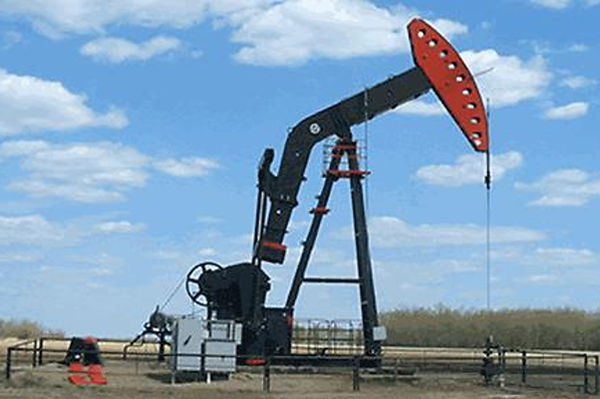
Figure 1. Beam or Sucker Rod Pump
Hydraulic Pumping
With this technology, a downhole hydraulic pump, rather than sucker rods, are used to lift oil to the surface. The production is forced against the pistons, causing pressure and the pistons to lift fluids to the surface. The natural energy within the well is used to raise the production to the surface. Hydraulic pumps can be waterjet, turbine, or piston based. Piston pumps are generally composed of two pistons, one above the other, which are connected by a rod that moves up and down within the pump. Both the surface and subsurface pumps are powered by oil, water or clean oil that has previously been removed from the well. The surface pump sends power oil through the tubing string to the subsurface pump which sends the reservoir fluids up a parallel tubing string to the surface. Figure 2 shows the schematic of hydraulic pumping.
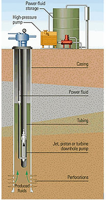
Figure 2. Hydraulic Pump
Gas Lift
With gas lifts, compressed gas is injected down the casing tube annulus of a production well, entering the well at numerous entry points called gas-lift valves. The injected gas reduces the pressure on the bottom of the well by decreasing the viscosity of the fluids in the well. This, in turn, encourages the fluids to flow more easily to the surface. Typically, the gas that is injected is recycled gas produced from the well. With very few surface units, gas lift is the optimal choice for offshore applications. As the gas enters the tubing at these different stages, it forms bubbles, lightens the fluids and lowers the pressure. Gas lift is an artificial lift process that closely resembles the natural flow process and basically operates as an enhancement or extension of that process. Figure 3 shows a schematic of the gas lift system.
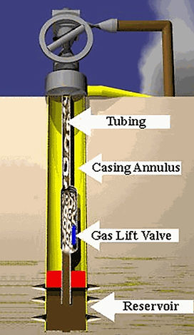
Figure 3. Gas Lift Schematic
Most applications of this technology involve the use of reservoir gas that is re-compressed for use as a lifting gas For very low gas to liquids ratios (GLR) this may not be feasible and another supply of gas may be necessary. Gas lift systems that inject gas into crude are sometimes used in conjunction with surface operating reciprocating pumps or horizontal centrifugal pumps. These systems require a supply of gas to be stored at the surface or the use of gas produced as lifting gas (by re-compressing). This requires additional compression capacity, which typically has high capital costs. In this type of system maintenance costs can also be high. Older gas-lift systems with high water cut are frequently being converted to ESP systems.
Electric Submersible Pumps (ESP)
Electric submersible pump (ESP) systems employ a centrifugal pump below the level of the reservoir fluids. The pumps are composed of several impellers, or blades that move the fluids within the well. The whole system is installed at the bottom of a tubing string. An electric cable runs the length of the well, connecting the pump to a surface source of electricity. Figure 4 shows a schematic of the ESP.

Figure 4. Electric Submersible Pump
Because ESPs can work with a variety of flow rates and depths, they are well-suited to work inside oil wells. When used accurately, an ESP pump can decrease well pressure at the bottom, enabling the withdrawal of a higher amount of oil than otherwise could be extracted under normal pressure conditions. Over the last several years, ESP technology has developed a reputation as a low-maintenance, cost-effective alternative to other surface applications in the petroleum industry. As a rule, ESPs have lower efficiencies with significant fractions of gas, typically greater than about 10 percent volume at the pump intake. As the amount of gas in the fluid approaches 10%, gas lock can occur. ESPs have been deployed in vertical, deviated and horizontal wells, but they should be located in a straight section of casing for optimum run life performance. On a cost-per-barrel basis, ESPs are considered economical and efficient.
Progressive Cavity Pumps
This technology is similar to the ESP in that progressive cavity pumps (PCPs) consist of a helical bore that rotates inside a similar helical cavity. The rotation of the bore creates cavities with negative pressure (vacuum) to open and close, forcing fluid up through the pump body. This technology has proven performance in crude oil at high viscosity. However, PCPs are vulnerable to damage from abrasive materials and are generally limited to well depths of approximately 5000 ft. and are limited to typical wells (e.g. wells without deviated or horizontal wellbores). The basic surface-driven PCP system configuration illustrated in Figure 5.
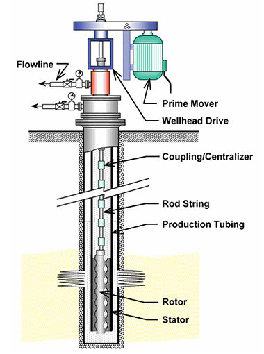
Figure 5. Progressive Cavity Pumps
Gas Wells
In mature gas wells, the accumulation of fluids in the well can impede and sometimes halt gas production. A common approach to temporarily restore flow in a gas well is to vent the well to the atmosphere which produces substantial methane emissions. At different stages in the life of a gas well, alternatives to repeated venting are deployed such as shutting-in the well to allow bottom hole pressure to increase, swabbing the well to remove accumulated fluids and installing an artificial lift system. Following are the primary artificial lift systems:
Plunger Lift
Plunger lifts are commonly used to lift fluids from gas wells. A plunger lift system is a form of intermittent gas lift that uses gas pressure buildup in the casing-tubing annulus to push a steel plunger and a column of fluid above the plunger up the well tubing to the surface. A valve mechanism and controller at the surface cause gas volume and pressure to build up in the wellbore initiating the plunger release cycle. At this point, the surface valve closes, and the plunger drops to the bottom of the well. Once adequate pressure is reached, the surface valve opens, and the plunger rises to the surface with the liquid load. Insufficient reservoir energy or too much fluid build-up can overload a plunger lift. When that occurs, venting the well to the atmosphere (well blowdown) instantaneously reduces the backpressure on the plunger and usually allows the plunger to return to the surface. Again, this can cause significant releases of methane emissions.
ESPs
Some gas reservoirs can produce a high amount of liquid, but because gas can damage ESPs, care must be taken when using an ESP to remove liquid from a gas well. However, ESP systems can be designed that enable the gas to flow freely up the pump’s casing, while the pump efficiently removes fluid. The gas flow depends largely on casing head pressure. Care must be taken sufficiently research the exact well situation for such uses before an ESP method is employed.
In the Western US, downhole submersible pumps are used for Coal-bed Methane (CBM) wells. There are an estimated 30,000 producing CBM wells in the US. Most coal seams with gas in commercial quantities contain water that is produced along with the gas. The coal zones typically require local or regional dewatering before commercial gas production can be achieved, and the key to economic production is cost-effective reservoir dewatering techniques. This has inherent problems as flows decrease, methane gas increases and coal fines are introduced into the wellbore. Traditionally, electrical submersible water well systems and rod-driven progressing cavity pumping systems (PCPs) have been employed to dewater CBM wells. However, reliability has been an issue with water well equipment, while cost considerations have stymied PCP and more rugged oilfield electrical submersible pumping systems. Newly designed hybrid ESP systems are more robust than water well systems are now being used for CBM wells.
PCPs
PCP systems have been used in CBM wells since 1986, both as the primary dewatering system and as a solution for troublesome wells, since PCPs can effectively pump coal fines, sand particles and gaseous fluids. Plus, PCP is a positive displacement system with the output rate directly tied to the speed of the pump. This feature allows the system to be adjusted via pump speed to match the decline curve of the water production, eliminating over-pumping the well.
Artificial Lift System Efficiencies
Artificial lift systems are served by separate pumping requirements. The use of more efficient pumping systems can have a significant impact on the cost of artificial lift systems. Optimizing production and decreasing costs require not only consideration of individual well characteristics and a lift system operational capability but also the cost of electricity.
Table 1 provides limitations for the selection of the type of artificial lift selected as well as overall system efficiencies

Table 1. Limitations for Selection of Artificial Lift Method
A comparison of four different types of pumping systems used in artificial lift is shown in Table 2. The table provides insight into the most efficient systems and therefore a relative sense of the efficiency of the pumping systems. The comparison is based upon a 5,000 ft well, a utility rate of $0.06 per kWh and 90% water cut.

Table 2. Artificial Lift Comparison Summary
A comparison of four different types of pumping systems used in artificial lift is shown in Table 2. The table provides insight into the most efficient systems and therefore a relative sense of the efficiency of the pumping systems. The comparison is based upon a 5,000 ft well, a utility rate of $0.06 per kWh and 90% water cut.
Additional notes
Plunger Lift - 20 + years but Electronic supervision, automation and optimization have created options that were not possible just a few years ago
Sucker Rod Pumps - 20+ years but sophisticated rod string design and better rod and coupler materials as well as pump rod controllers has made use of the technology more tolerable to rod dynamics in recent years. Recent improvements in motor technology and use of VFDs has helped improve efficiency
Hydraulic Pumping – 20+ but recent use of natural gas rather than diesel fuel as well as dual fuel has significantly reduced costs as well as emissions
Gas Lift - 20+ years but emerging technology being used for offshore applications due to few surface units. Represent about 10% of US market
ESP – 20+ years but are the fastest growing pumping technology. Represent about 15 to 20 percent of worldwide market. Monitoring, diagnosis and control have proven to maximize efficiency in recent years. Hybrid ESP/PCP systems have recently been developed. These systems facilitate the handling of viscous and abrasive fluids, increase the flow rate as well as improve efficiency
PCP – 20+ years for both on-shore and off-shore applications. In recent years, use of efficient permanent magnetic motors and innovative torque converters has shown gains in efficiency and costs as well as use in more diverse environments. Motor technology and use of VFDs – 5 to 10 yrs. Use of these technologies have helped improve efficiency

API: The API gravity, or API degrees, of its acronym in English American Petroleum Institute, is a measure of density that, compared to water at equal temperatures, specifies how heavy or light oil is. Indexes greater than 10 imply that they are lighter than water and, therefore, would float in it.